Prepare a 10mm hex wrench and ensure you power off the vehicle in the safety settings.
After removing the original airbag and replacing the wheel body, the recommended torque for the fixing bolt is 60Nm.
Installation takes approximately 30 minutes. The critical step involves entering Service Mode to modify the configuration, ensuring the turn signal logic and software are perfectly adapted.
Installation
Installation involves power disconnection of the 12V or 16V low-voltage system and SRS airbag migration.
Required tools include a T55 Torx socket, a 10mm hex wrench, and a torque wrench with a range covering 80Nm.
Before operation, execute "Power Off" on the vehicle screen and wait at least 10 minutes to ensure capacitor discharge.
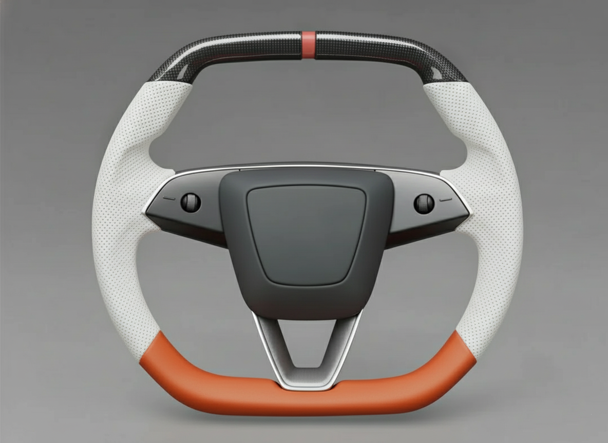
The weight of a Yoke typically ranges between 1.2kg and 1.8kg. During installation, align with the spline markings and ensure the heating wire resistance remains within the 1.5 to 2.1 ohm range to avoid electrical offset in the driver module.
Essential Tools
The primary tool is the T55 Torx socket, which is the only specification for removing the steering column center bolt.
This bolt is coated with high-strength blue thread locker at the factory. The breakaway torque during removal often exceeds 100Nm; therefore, the T55 socket must be made of S2 alloy tool steel with a hardness of HRC58 to HRC62 to prevent stripping or breakage under sudden force.
It is recommended to use a 1/2-inch (12.7mm) drive heavy-duty ratchet wrench with a handle length exceeding 250mm, utilizing physical leverage to counteract the resistance of the thread locker.
Airbag removal requires a 10mm diameter long-handle hex wrench or a flat-head telescopic rod of the same specification.
The Model 3's airbag fixing mechanism consists of two steel wire spring clips hidden inside the steering base, with an aperture depth of approximately 60mm to 80mm.
The selected tool length must exceed 150mm, and the rod diameter must not exceed 10mm; otherwise, it will get stuck on the edge of the service hole in the steering column trim.
During operation, one must sense the feedback pressure of the metal spring, which has a compression travel of about 15mm.
If the tool's hardness is insufficient and it bends, it will fail to generate enough thrust to disengage the airbag clip.
| Tool Name | Core Parameters & Specifications | Industrial Standard / Data Indicator | Specific Use Details |
|---|---|---|---|
| T55 Torx Socket | 1/2-inch drive, S2 steel | Approx. HRC60 hardness | Removing and installing the steering column center bolt |
| Torque Wrench | 10Nm - 100Nm range | ISO 6789 calibration error < 4% | Accurately executing the 80Nm tightening command |
| 10mm Removal Rod | Length > 150mm, cylindrical | Polished surface | Passing through side holes to push SRS airbag springs |
| Digital Multimeter | 200 ohm resistance range | 0.1 ohm precision | Measuring Yoke heating wire and LIN bus resistance |
| 10mm Socket/Wrench | Ratchet or combination type | Fits 12V/16V battery terminals | Rapidly disconnecting the low-voltage power supply |
| Nylon Pry Bar Set | Shore A 90 hardness, 5-piece set | Scratch-resistant high-strength POM | Detaching steering wheel back cover and stalk shroud |
| Extension Bar | 3-inch and 5-inch specs | 1/2-inch interface | Avoiding dashboard space constraints for operation clearance |
A torque wrench is a critical tool for structural safety; using a standard ratchet for final tightening is strictly prohibited.
The Tesla service manual explicitly specifies a tightening torque of 80Nm for the center bolt.
The selected torque wrench range should cover 20Nm to 100Nm to ensure linear accuracy in the high-value range.
If the torque is below 70Nm, high-frequency vibrations during driving may lead to increased steering backlash.
If it exceeds 90Nm, it may cause metal fatigue in the steering column spline seat or tensile deformation of the bolt.
Before each use, confirm the tool is calibrated, with the error controlled within ±3.2Nm.
For circuit matching, a digital multimeter is an indispensable testing device.
Yoke steering wheels typically integrate capacitive sensing and electric heating functions.
The DC resistance of the original heating module is 1.5 ohms to 2.1 ohms at room temperature (approx. 20°C).
Before installation, the multimeter must be set to the 200-ohm range to measure the resistance of the heating positive and negative poles in the Yoke harness terminal.
If the measured data is below 1.0 ohm, connecting it to the system will cause the Temperature Control Unit (TCCU) to cut output due to overcurrent protection.
If it is higher than 3.5 ohms, the vehicle will report an open circuit fault for the heating loop.
Simultaneously, check the insulation resistance between the LIN bus data line and the shield line to ensure it remains at infinity, preventing button signals from electrostatic interference.
| Measurement / Physical Item | Target Value & Quantifiable Standard | Data Tolerance Range | Consequence of Abnormality |
|---|---|---|---|
| Center Bolt Torque | 80 Newton Meters | +/- 5Nm | Steering column loosening or thread stripping damage |
| Heating Wire Resistance | 1.8 Ohms | 1.5 - 2.1 Ohms | Vehicle displays heating function temporarily unavailable |
| Discharge Static Time | 10 Minutes | Minimum 600 seconds | Residual voltage in SRS capacitors triggers accidental deployment |
| Spline Displacement | 0 tooth offset | Angular deviation < 0.5 degrees | Off-center steering wheel or loss of calibration when straight |
| Battery Terminal Torque | 5Nm | 4.5 - 6Nm | Poor power contact causing low-voltage supply issues |
| Pry Bar Thickness | 1.5mm wedge end | Edge R-angle < 0.2mm | Permanent compression deformation at trim joints |
When removing interior trim panels, prepare a set of high-density nylon pry bars rather than metal screwdrivers.
The Model 3's steering wheel back cover is made of PC+ABS alloy, and its surface leather grain is easily scratched by hard objects.
The Shore hardness of the pry bar should be between A85 and A95, providing enough support to pry open internal plastic clips without leaving whitening marks on the trim edges.
When handling airbag harness connectors, a small precision flat-head screwdriver (blade width 2.0mm) is needed specifically to lift the yellow safety CPA (Connector Position Assurance) locks.
The unlocking force for these connectors is typically between 5N and 8N; maintain a vertical upward force during operation to prevent wear on the internal gold plating of the pins, which could cause impedance fluctuations in future signal transmission.
For Model 3 vehicles from different years in North American or European markets, low-voltage connector locations may vary. Therefore, it is recommended to prepare a powerful flashlight with a brightness of over 500 lumens to observe the 12V battery negative terminal under the frunk or the emergency power-off loop under the rear seat.
After physical power disconnection, use a multimeter's DC voltage setting to measure the cigarette lighter port or 12V supply terminal to confirm the voltage has dropped below 0.5V.
This quantified confirmation of power-off is the safety baseline for handling SRS airbag components, avoiding any system misjudgment due to residual energy.
After use, all tools should be returned to their places according to specifications, especially the pairing of the T55 socket and torque wrench, as these may still be needed for torque re-inspection during periodic checks every 20,000 miles.
Disconnecting Power Supply
Since the Yoke steering wheel modification involves removing the SRS (Supplemental Restraint System) airbag, failing to cut the low-voltage loop may cause the Airbag Control Unit (ACU) sensors to detect resistance fluctuations or connector plugging, generating error signals or even triggering the initiator in extremely rare cases.
The first step must be a software shutdown via the vehicle screen. On the touchscreen, click "Safety" > "Power Off".
During this operation, the person must remain inside the vehicle without stepping on the brake pedal, opening the door, or touching any physical buttons.
Observe the screen turning black; the high-voltage contactors will emit a distinct metallic "clunk," indicating the high-voltage battery has been physically detached from the DC-DC converter, and the vehicle has entered deep sleep.
To ensure safety, physical low-voltage disconnection is mandatory.
Open the front trunk (Frunk) and remove the rear maintenance cover to expose the low-voltage battery area.
For models equipped with a 12V lead-acid battery, prepare a 10mm ratchet wrench to loosen the nut on the negative terminal.
Note that the nut does not need to be completely removed; simply loosen it until the terminal can rotate freely on the post.
Pull out the negative cable and wrap it in an insulating cloth to prevent it from accidentally snapping back and contacting the metal body, causing an arc discharge.
If the vehicle is a newer model equipped with a 16V lithium battery, the disconnection is performed by unplugging the dedicated gray connector near the frunk air intake grille.
| Power System Component | Specs & Voltage Parameters | Physical Location | Power-Off Logic |
|---|---|---|---|
| High-Voltage Battery | 350V - 400V DC | Under the vehicle chassis | Close contactors via vehicle software |
| 12V Lead-Acid Battery | 12.6V - 12.8V | Under frunk rear cover | Disconnect negative terminal with 10mm tool |
| 16V Lithium-Ion Battery | 15.5V Nominal | Near frunk air intake | Unplug low-voltage loop connector |
| HV Interlock Loop (HVIL) | Low-current sensing loop | Frunk or under rear seat | Pull out emergency switch with red tab |
| SRS Backup Capacitor | Maintains power for ~500ms | Inside Airbag Control Module | Natural discharge via 600-second wait |
After cutting low-voltage power, the high-voltage emergency power-off loop must be addressed.
The purpose of this loop is to send a physical shutdown command to the vehicle's energy management system.
In the Model 3 frunk area, a wire loop plug with a red label can usually be found.
Pull it out or cut it according to the label instructions.
This action triggers an open circuit in the High-Voltage Interlock Loop (HVIL), causing the contactors inside the high-voltage battery pack to remain in a permanently open position. Even if the vehicle system is accidentally awakened, high-voltage current cannot enter the cabin's AC or heating systems.
For some early production models in the North American market, this loop may be located next to the foam padding under the rear seat cushion; the cushion needs to be pulled up to release the clips before it can be reached.
After completing the physical disconnection, waiting for 10 minutes (600 seconds) is an unnegotiable rigid requirement.
This duration is determined by the discharge characteristics of the electrolytic capacitors inside the Airbag Control Unit (ACU).
According to Tesla's circuit logic, the SRS system is designed with secondary energy storage to ensure sufficient power to blow the airbag in the event of a collision that instantly destroys the battery.
The voltage of these residual charges is typically between 12V and 15V, and it takes a specific time period to drop to a safe level below 0.5V through discharge resistors.
While waiting, observe the state of the windows. Tesla doors use a frameless design; when a door is opened, the window automatically drops about 10mm to 15mm.
| Electrical Operation Indicator | Quantified Standard | Error Tolerance Range | Status Confirmation Method |
|---|---|---|---|
| Power-Off Static Duration | 600 Seconds | Minimum 10 minutes | Strict monitoring with a timer |
| Battery Terminal Torque | 5.5 Newton Meters | 5Nm - 7Nm | Use torque wrench during reassembly |
| Auxiliary Discharge Voltage | Below 0.5V DC | 0V - 0.5V | Measure cigarette lighter port with multimeter |
| Window Pre-drop Displacement | 10 mm | 8mm - 12mm | Confirm glass has dropped before power-off |
| Environmental Humidity | Below 65% RH | 40% - 70% | Prevent condensation at HV interfaces |
After the wait period, it is recommended to use a multimeter's DC voltage setting for final safety confirmation.
Contact the probes with the positive and negative poles of the cigarette lighter power supply or measure the residual voltage of the frunk low-voltage terminals.
If the reading shows 0.0V or below 0.2V, the entire vehicle potential has dropped to ambient background levels.
At this point, the vehicle's Electronic Steering Column Lock will be in a locked or freely rotating state (depending on the steering wheel position at the moment of power-off).
Throughout the power-off process, the operator's body should be free of static electricity; one can discharge their own charge by touching the vehicle's metal frame or a grounding wire first.
Disconnecting power is not only to protect the airbag but also to protect the Model 3's extremely sensitive LIN bus and bus transceivers.
Data communication for steering wheel scroll wheels and heating modules relies entirely on these weak voltage signals; any plugging or unplugging while powered may cause the Gateway to record permanent hardware communication fault codes.
-
Execute Vehicle Software Shutdown
- Maintain driving position and close all apps.
- Click "Power Off" in the Safety menu.
- Wait for the screen to go completely dark after hearing the "clack" of the contactors.
-
Disconnect Low-Voltage Physical Connection
- Open the hood and remove the maintenance panel.
- Locate the 12V or 16V battery interface.
- Use a 10mm socket to loosen and separate the negative terminal, ensuring the harness end does not touch metal.
-
Release High-Voltage Interlock Loop
- Locate the "First Responder Loop" with the red label.
- Press the release button and pull the plug outward.
- Confirm the plug is fully detached and pins are clear of debris.
-
Enforce Discharge Waiting Period
- Set a 10-minute countdown.
- Prohibit connecting any external chargers or stepping on the brake pedal during this time.
- Confirm emergency lights, ambient lights, and dashboard displays are completely off.
After the low-voltage system is disconnected, the vehicle's security alarm and sensors will also be disabled, so construction should take place in a closed private garage or workshop.
If you need to leave halfway through the modification, ensure the doors are closed manually. This state of total vehicle power loss must be maintained until the Yoke steering wheel is connected.
This quantified power interruption scheme avoids over 99% of electronic system logic conflicts, providing a completely silent electrical environment for the subsequent T55 center bolt removal and airbag harness migration.
Removing Airbag Module
The Tesla Model 3 airbag is not secured by bolts but relies on a set of high-tension metal spring clips locked into the die-cast aluminum frame of the steering base.
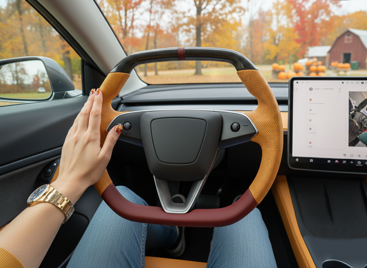
At the 3 o'clock and 9 o'clock positions on the sides of the steering wheel, there are two circular service holes approximately 6mm in diameter.
A cylindrical steel rod or hex wrench with a length of no less than 150mm and a diameter of 10mm should be used.
When the tool is inserted horizontally into the hole, it will encounter the internal steel wire spring. This spring has a compression stroke between 12mm and 15mm and requires a linear thrust of about 15N to 25N.
Due to the strong rebound force of the spring, a distinct metallic damping sensation should be felt. When the thrust overcomes the spring tension and shifts it toward the center, one side of the airbag module will automatically pop outward by about 10mm due to internal pressure.
Subsequently, maintain the steering wheel position and perform the same pushing action on the other side, ensuring both hooks of the airbag module are fully disengaged from the locking positions of the steering base.
Once the airbag module is loose, do not pull it outward with force, as the back is still connected to precision data cables and initiator trigger wires.
Gently flip the airbag module upward; two sets of brightly colored electronic connectors, typically yellow and orange, will be visible.
These colors represent the dual-stage trigger logic of the airbag, used to determine inflation speed based on collision force.
Each connector has a black Connector Position Assurance (CPA) lock on top. Use a precision flat-head screwdriver with a 2mm blade to gently lift this black lock about 3mm; the connector is now unlocked.
Then pull the connector vertically upward with a force of 5N to 10N, avoiding diagonal force to prevent pins from bending or breaking.
In addition to the two main trigger lines, a thin purple or black ground wire is usually connected to the bottom of the airbag module.
This ground wire uses a 4.8mm spade connector. Due to long-term fastening, the connector may have resistance from oxidation; it is recommended to use a nylon pry bar to assist in pushing it out, and it is strictly forbidden to pull directly on the wire insulation.
| Removal Parameter Item | Quantified Data / Specification | Technical Description |
|---|---|---|
| Side Service Hole Diameter | 6.5 mm | Fits tools under 10mm diameter |
| Internal Spring Travel | 12 - 15 mm | Exceeding this travel causes permanent spring deformation |
| Trigger Line Spec | 2-Stage (Dual-Plug) | Distinguished by yellow and orange coding |
| CPA Lock Travel | 3 mm | Lift to unlock, no need to remove |
| Pin Contact Resistance | Below 0.05 Ohms | Ensures lossless transmission of initiator current |
| Ground Terminal Spec | 4.8 mm Spade | Responsible for ESD discharge and horn circuit grounding |
| Recommended Force | 15 - 25 N | Simulates pressing a medium-hardness spring by hand |
After removing all cables, the storage of the airbag module must comply with North American SAE safety standards. The airbag's decorative cover (the side with the Tesla logo) must be placed facing upward on a dry, insulated surface, such as a rubber mat or short grass.
This placement prevents the metal airbag base from flying upward like a projectile due to reaction force in the extremely unlikely event of an accidental deployment, which could cause serious injury.
At this point, also observe the state of the clockspring (spiral cable) in the center of the steering wheel. This component transmits power from the stationary steering column to the rotating steering wheel.
Without the airbag covering it, the transparent plastic rotor of the clockspring becomes very fragile. It is strictly forbidden to randomly rotate the clockspring after the airbag is removed; the rotation limit of its internal flat cable is typically 2.5 turns in each direction.
If the clockspring deviates from the center alignment point, when subsequently installing the Yoke and performing full-turn operations, the internal harness will break due to over-stretching, leading to horn failure, unresponsive buttons, or a permanent SRS warning light.
-
Locating Side Holes and Tool Alignment
- Rotate the steering wheel to the center position, ensuring the service holes are on a horizontal axis.
- Look into the hole with a flashlight to confirm the edge of the metal spring, avoiding the tool slipping into the foam layer.
- Insert the 10mm removal tool fully until a metal-on-metal collision is felt.
-
Two-Stage Unhooking Logic
- Hold the wheel at 9 o'clock with the left hand and push the 3 o'clock spring with the tool in the right hand; observe the right side of the airbag popping out.
- Once one side pops out, do not press it back, or it will re-lock.
- Repeat for the other side until the airbag is completely floating.
-
Precision Harness Decoupling
- Support the airbag module with one hand to prevent its weight from hanging on the harness and damaging connectors.
- Use a precision screwdriver to lift the CPA safety tab; a "click" indicates it has risen 3mm.
- Pull the yellow and orange plugs vertically, checking the sockets for erosion or contamination.
-
Module Isolation and Protection
- Move the removed airbag out of the cabin and place it in a safe location at least 2 meters away from the work area.
- Check the interior of the steering base for loose plastic debris; debris falling into the clockspring gap will cause rotational noise.
- Visually mark the spline area of the steering column to record the original alignment scale.
When handling SRS modules, static electricity from human skin can exceed 2000V in dry environments; while insufficient to detonate the initiator directly, it can damage the tiny filtering inductors inside the connectors.
It is recommended to touch the door hinge or other exposed metal parts of the vehicle to discharge before touching the airbag.
When observing the production label on the back of the airbag module, one can confirm its manufacturing date and batch information. The Model 3 uses an advanced guanidine nitrate-based non-sodium azide gas generator, which is relatively stable chemically.
Before installing the Yoke, compare the geometric dimensions of the original wheel and the new Yoke at the airbag installation site.
The original aluminum frame's hole precision is typically within ±0.1mm. If the Yoke's casting mold precision is insufficient, the spring clips will not reset smoothly under the 80Nm center bolt compression, resulting in a stiff horn press or delayed rebound.
Inside the steering base cavity after removing the airbag, you will see the central distributor for the scroll wheels and heating module.
This distributor connects to the clockspring via a multi-pin white plug.
In the subsequent steps, this distributor needs to be migrated from the old wheel to the Yoke. At this point, measure the length of the harness leading from the distributor to ensure there is enough routing space within the Yoke's narrower spokes.
Any pinched cable will suffer insulation damage during long-term steering friction, leading to a short circuit to ground in the 15.5V low-voltage system.
If the Yoke body has a carbon fiber lining, pay special attention to whether the edges are polished smooth to prevent them from cutting the airbag trigger wires like a blade.
All small parts removed, including the airbag connector safety clips, should be placed in a magnetic parts tray to avoid loss during the cumbersome wheel swap, as these are OEM parts not sold separately.
Fastener Torque
The center bolt is manufactured from M14 specification Class 10.9 high-strength steel, featuring a T55 Torx drive interface.
This design is intended to transmit massive torque within a very small contact area to overcome the high-strength blue micro-encapsulated thread locker pre-applied to the threads at the factory.
During removal, the initial breakaway torque can soar to between 95Nm and 110Nm due to the viscosity of the thread locker.
The operator must use a 1/2" drive wrench or breaker bar with a length of no less than 350mm to counteract this resistance via leverage.
It is strictly forbidden to use the steering column's electronic lock to secure displacement during removal, as 100Nm of shear force could deform or break the internal locking pin. The correct method is to have an assistant firmly hold the wheel rim or use one's knees against the lower edge, ensuring the T55 socket is 180 degrees perpendicular to the bolt axis to prevent torque deviation and stripping of the Torx slots.
The tightening specification for the center bolt is set by Tesla engineering as a constant 80Nm (approx. 59 lb-ft).
This value is calculated based on the yield strength of the steering column's aluminum spline base and the pre-tension curve of the steel bolt.
When the torque reaches 80Nm, the bolt undergoes a slight elastic elongation, generating sufficient normal force between the threads to lock the tapered mating surfaces of the steering wheel and steering shaft.
If the actual torque is below 70Nm, long-term road vibrations and reciprocating steering movements may cause the bolt to back out slightly due to alternating stress, resulting in blurred steering feel or play.
Conversely, if torque is blindly increased to over 100Nm, it exceeds the proportional limit of the threads, potentially causing plastic flow in the internal threads of the steering column or reducing the fatigue strength of the bolt itself, creating hazards for future disassembly and maintenance.
| Fastener Physical Item | Specification & Quantified Standard | Data Tolerance & Technical Range | Physical State & Safety Impact |
|---|---|---|---|
| Center Bolt Spec | M14 x 1.5 Pitch | Class 10.9 Steel | High-grade carbon alloy steel, tensile strength 1040MPa |
| Drive Type | Torx T55 | 6-Point Star | Optimized force distribution to prevent slipping |
| Official Standard Torque | 80 Newton Meters | +/- 5Nm | Ensures full spline engagement without overstressing |
| Thread Locker Requirement | Medium/High Strength | Blue Micro-encapsulated | Prevents radial backing out from heat and vibration |
| Steering Column Splines | 48 Teeth (Typical) | 1:1 Fitment | Determines absolute angle correlation with steering rack |
| Bolt Length/Travel | Approx. 35mm | Effective thread length 25mm | Deep entry ensures over 5 full turns of thread engagement |
When pushing the Yoke steering wheel onto the column, the spline alignment must be controlled to 0 tooth deviation.
The steering column usually has a fine vertical centerline engraved, and the Yoke's aluminum center seat corresponds with a casting mark.
If the alignment is off by even 1 tooth, the Model 3's steering ratio will cause a steering wheel deviation of 5 to 8 degrees when driving straight, which affects visual perception and interferes with the Autopilot system's path planning logic due to a continuous zero-point offset detected by the Steering Angle Sensor (SAS).
Before tightening the bolt, use fingers to screw the bolt in for 3 to 5 turns to confirm no cross-threading has occurred, then use a correctly calibrated torque wrench.
The torque wrench must comply with ISO 6789 international standards and be within its valid calibration cycle. When performing the final 80Nm tightening, apply force in a smooth, continuous manner and stop immediately when the wrench "clicks".
Strictly avoid secondary "nudging" or double-clicking, as static friction is greater than dynamic friction; secondary nudging can cause the actual torque to exceed the set value by more than 10%.
For Yoke aftermarket parts, because some aluminum alloys may have an 5% to 10% hardness deviation from OEM parts, it is recommended to wait 5 minutes after reaching 80Nm for micro-stress release between the metals, then perform a torque re-check to ensure the reading remains stable within the target range.
- Alignment Verification Logic: Slide the Yoke onto the spline and shake it slightly before installing the bolt. Confirm the tooth engagement depth; there should be no obvious radial play, and the angular deviation should be less than 0.5 degrees.
- Thread Cleaning: Use compressed air or anhydrous ethanol to clean the internal threads of the steering column. Remove residual old thread locker to ensure the new bolt or reapplied locker achieves 100% chemical bonding area.
- Torque Application Curve: Tighten in two stages—first pre-tighten to about 30Nm with a standard wrench to observe alignment and levelness, then achieve 80Nm in one smooth motion with the torque wrench.
- Temperature Consideration: Metal expands and contracts. in extreme cold (below 0°C), it is recommended to heat the cabin to about 20°C using the AC to allow steering column components to return to standard dimensions, preventing low-temperature brittleness from affecting thread capacity.
- Harness Clearance Check: Before final locking, use a flashlight to check if the T55 bolt washer is compressing the heating module or the LIN bus cable for the scroll wheels. The cable diameter is approx. 1.2mm; if flattened, it creates an instantaneous short circuit risk.
After completing the 80Nm standard tightening, it is recommended to use a marker to draw an alignment paint mark across the bolt head and the steering wheel frame. After driving for 500 miles (approx. 800 km), perform a quick visual inspection by removing the airbag module.
If the paint mark has not shifted, it proves the torque state is well maintained.
This data-driven management is a Standard Operating Procedure (SOP) in North American automotive maintenance, maximizing safety by minimizing the risk of steering loss due to fastener failure.
Coding
Connect to the Tesla Toolbox 3 diagnostic system via the 100BASE-T1 Ethernet interface to switch the SteeringWheelType parameter in the Gateway from Standard to Yoke.
This change triggers a 3D rendering model update on the 15-inch central screen and resets the steering rack feedback logic.
Subsequently, a system re-flash taking about 40 minutes is required to download and overwrite the approx. 2.5GB firmware package. This eliminates potential communication latency in the Autopilot module (within 200ms) and ensures 100% matching of heating resistance and button mapping.
Diagnosis Link Setup
The Model 3 does not use the traditional OBD-II protocol for deep coding but is based on the 100BASE-T1 automotive-grade Ethernet standard.
This differential signal transmission requires physical connections with high anti-interference capability and impedance matching.
For models produced from 2021 onwards equipped with AMD Ryzen processors, the diagnostic port is usually located inside the passenger-side center console; a plastic side panel must be removed to see the dedicated 4-pin or 6-pin connector.
This interface leads directly to the Media Control Unit (MCU). Using a specific harness adapter converts it to a standard RJ45 Ethernet port, allowing a laptop to join the vehicle's internal LAN.
When connecting, the laptop's network card should be manually configured with a static IP address, typically in the 192.168.90.x subnet (e.g., 192.168.90.100) with a subnet mask of 255.255.255.0 to establish a handshake with the vehicle's default gateway address (192.168.90.10).
| Physical Link Component | Detailed Technical Specs | Physical Deployment Location & Function |
|---|---|---|
| Diagnostic Adapter Cable | 4-Pin or 6-Pin to RJ45 adaptive cable | Accessing MCU internal Ethernet nodes, impedance controlled at 100 ohms |
| Ethernet Card | USB-C adapter supporting 10/100/1000 Mbps | Physical interface on the laptop side; models with ASIX chips recommended |
| External Stabilized Power | 13.8V output, current ≥ 30A | Continuously connected to 12V/16V battery to prevent voltage drop below 11V during flashing |
| Network Cable | Cat6e or Cat7 shielded twisted pair | Length should not exceed 5 meters to maintain signal integrity and reduce EMI |
Because the Model 3 maintains a high load on sensors, computing units, and cooling pumps while in Service Mode to execute parameter changes, the vehicle's static power consumption can spike to between 300W and 800W.
Relying solely on the vehicle's own low-voltage battery (especially the 16V lithium battery in newer models) may drain the power within 20 minutes, causing an abnormal power failure while the gateway is writing the SteeringWheelType parameter.
If power fails, the gateway's configuration dictionary may suffer a Checksum error, preventing the vehicle from entering drive mode.
Therefore, connecting a 13.8V stabilized charger in parallel is a mandatory technical requirement.
After successful connection, access the Toolbox 3 diagnostic platform via Chrome. The system establishes real-time bidirectional communication with the vehicle via the WebSocket protocol.
At this point, the laptop acts not just as a display terminal but as a firmware distribution node. During re-flash, the approx. 2.5GB compressed data package is downloaded from the cloud to the laptop's memory and pushed to the vehicle's ECUs at nearly 100Mbps full-duplex speed via the diagnostic cable.
| Diagnosis Status Parameter | Normal Operating Range / Value | Impact of Deviation |
|---|---|---|
| Network Latency (Ping) | < 5ms (to gateway address) | Over 50ms causes Toolbox 3 to disconnect frequently |
| Low-Voltage System Voltage | 12.8V - 14.4V | Below 12.0V triggers system protection, interrupting config writing |
| Data Bandwidth | Effective throughput ~85Mbps | Insufficient bandwidth leads to decompression failure or 2x longer duration |
| Connection Protocol | TCP/IP stack based on 100BASE-T1 | Poor physical connection generates high volumes of CRC error frames |
In terms of physical topology, the diagnostic link bypasses the regular layers of the center screen to enter the developer's debug channel.
For older Model 3s with Intel Atom processors, the interface may be located at the maintenance window below the glovebox.
In this case, the pinout of the diagnostic cable differs from the newer version; incorrect wiring sequence will burn the MCU's Ethernet transceiver.
In practice, when the RJ45 interface LED starts flashing at 1Hz, the physical handshake of the link layer is complete.
Subsequently, the Toolbox 3 plugin on the browser side will automatically detect the vehicle's VIN.
If the connection is stable, the platform's "Vehicle Tree" will display the online status of all internal buses, including CAN-Bus and LIN-Bus activity frequencies.
Only when the Gateway icon shows green without active alerts can the Yoke steering wheel parameter mapping proceed.
Any physical loose contact or impedance offset will trigger a U0100-type communication loss fault code at the moment of modifying SteeringWheelType, causing the task to fail.
To ensure the 40-minute encoding and firmware deployment process is not interrupted, the laptop's OS must disable all sleep and power-saving options.
Wi-Fi should be turned off as a backup link, forcing all data traffic through the USB Ethernet adapter.
For North American or European market vehicles, Toolbox 3 access usually requires activation through a Tesla official partner account or temporary subscription.
If IP acquisition fails during link establishment, check if the vehicle is in "Stay Awake" mode.
This can be done by turning on the AC or keeping the driver's door ajar to prevent the vehicle from entering deep sleep.
This long-term physical connection is the prerequisite for all software configurations, ensuring every bit of data is accurately written into the gateway's non-volatile memory during the Update Config operation.
Bottom-Level Parameter Modification
After logging into the Tesla Toolbox 3 platform and successfully establishing the 100BASE-T1 connection, the process shifts from "Read" to the "Write" phase.
The dashboard interface on the laptop browser will list all current vehicle configuration variables.
Locate the module named CarConfig, which is the non-volatile storage area for vehicle hardware features.
Every variable corresponds to a specific storage address in the Gateway, controlling everything from motor power output to interior component rendering.
Input SteeringWheelType in the search box; the system will return the current value, which is usually Standard (round wheel) for a Model 3.
This variable is more than just a label; it is linked to a complex set of hexadecimal offsets in the bottom-level code, affecting the Autopilot computer's (HW3.0 or HW4.0) judgment thresholds for driver hands-off detection (Torque Sensor).
By clicking the dropdown menu to switch the value from Standard to Yoke, you are essentially preparing a new configuration image.
In Yoke mode, where the physical obstruction area is reduced, the system sends new instructions to the Media Control Unit (MCU) to call the Yoke 3D model resource files stored on the memory chips.
This process involves JSON-formatted data exchange. Toolbox 3 generates a difference list comparing old and new parameters. Before clicking "Apply Changes," ensure the vehicle is in Park (P) with the Electronic Parking Brake (EPB) locked.
The system performs a CRC32 cyclic redundancy check on the new configuration string to ensure no bit flips occurred due to EMI during transmission. If validation fails, the gateway rejects the write operation and returns a 0x1F format service rejection code.
| Parameter Variable Name | Original Default Value | Modification Target Value | Bottom-Level Logic Change |
|---|---|---|---|
| SteeringWheelType | Standard | Yoke | Changes dashboard model, adjusts steering torque sensor alarm thresholds |
| SteeringRackType | Varies by VIN | No Change | Maintains existing steering rack ratio to avoid offset errors |
| HapticFeedback | Enabled | Enabled | Maintains vibration feedback frequency during lane departure |
| HeatedWheel | Optional | Match Hardware | Synchronizes based on whether the installed Yoke has heating hardware |
Once the operator confirms and executes the modification, the gateway enters a temporary "Configuration Mode."
During this time, CAN Bus communication will experience a brief silence of about 500ms to 1500ms.
In this window, the new configuration is written into the Gateway's flash memory. Upon completion, the vehicle will perform several reset actions, including momentary AC fan stoppage and screen flickering.
This is because the gateway is broadcasting the new hardware list to over 40 ECUs throughout the vehicle. Every ECU receiving the broadcast adjusts its operating mode according to the SteeringWheelType = Yoke command.
For example, the Body Control Module (BCM) redefines the heating loop duty cycle, as the Yoke steering wheel's heating wire length and impedance differ physically from the round wheel by approx. 15% to 20%.
Failing to perform this modification while using physical heating buttons could cause the heating control module to detect impedance abnormalities, triggering a DI_f048-type overcurrent protection fault code.
-
Configuration Verification Phase: After a successful write, the Toolbox 3 status bar turns from yellow to green, showing
Config Synced. Check if the real-time feedback for theGTW_steeringWheelTypesignal is indeed0x02. -
Communication Integrity Check: Observe if the gateway reports any custom fault codes other than
U0100orU0101. IfConfig Mismatchappears, the current firmware version does not contain the Yoke resource package. - Safety Signature Validation: Some security updates for North American or European markets require modifications to be signed online via Tesla's servers. The laptop must maintain a 4G/5G or stable Wi-Fi connection to obtain temporary authorization tokens from the server.
-
Data Rollback Strategy: Before modification, Toolbox 3 automatically exports an original config file with a
.jsonsuffix. If "Power Steering Disabled" occurs after modification, the operator must complete a config rollback using this backup within 30 seconds.
In Model 3 software logic, the next step after modifying SteeringWheelType is forcing the system to re-evaluate whether its software copy matches the new hardware configuration.
This matching is based on a multi-layered mapping of the VIN (Vehicle Identification Number) and hardware IDs.
For AMD Ryzen-equipped vehicles, this involves an integrity scan of the approx. 12GB on-board flash space.
If high-resolution UI textures for the Yoke or specific steering curve maps are missing from local cache, the system will mark the state as "Firmware Inconsistency."
| System Response State | Phenomenon Description | Processing Logic |
|---|---|---|
| Pending Update | Yellow alarm clock icon appears on screen | System recorded config, awaiting firmware re-flash to activate |
| Config Success | Vehicle 3D model instantly changes to Yoke | Limited to specific software versions; usable without re-flash |
| Signature Error | "Access Denied" warning pops up | Token expired or write failure due to insufficient account permissions |
| Hard Reset | Center screen goes completely black and reboots | Vehicle is performing a full-bus reset; wait 2 minutes |
An often overlooked detail in parameter modification is the Steering Angle Sensor (SAS) reset.
Because there might be tiny physical deviations during Yoke installation (e.g., spline offset by 1-2 degrees), the gateway clears previous zero-point calibration data after switching to Yoke.
After encoding, the steering wheel might appear slightly skewed when straight, or Autopilot may fail to engage.
The operator must execute the SAS_Calibration action in the Toolbox 3 menu, which sends a 0x28 diagnostic command to the steering column control module, forcing it to establish a new zero-point at the current position.
This requires the vehicle to be on absolutely level ground with tire pressure deviations not exceeding 0.5 PSI between left and right.
In the final stage of parameter writing, it is recommended to review all vehicle parameters via the "Config Comparison" function.
Ensure no other variables were accidentally modified besides SteeringWheelType.
For example, some automated scripts might incorrectly change AutopilotHardware or RestraintSystem types, which could trigger emergency braking or airbag faults during driving.
Once confirmed, return to the main menu; the system will generate a Post-Config Report, recording the precise timestamp, operator ID, and HEX code differences. This report is a vital reference for future official service, as any CarConfig change is permanently recorded in the vehicle's Blackbox memory.
System Firmware Re-flash
After modifying SteeringWheelType in the gateway, the Model 3 OS does not spontaneously update its GUI or control algorithms.
A system firmware re-flash is required to let the vehicle re-download and overwrite the current software based on the latest Car Config. This is not a simple reboot; it involves the coordinated refreshing of 40 to 60 ECUs.
For AMD Ryzen models, the full firmware package is typically 2.5GB to 3GB, while a full filesystem integrity check can involve up to 12GB of data traffic.
Enter the "Software" menu on the screen, long-press the "Model 3" icon for ~3 seconds, and input service in the dialog box to enter Service Mode.
In the "Software" tab of Service Mode, find the "Software Reinstall" button to trigger the firmware reconstruction.
Executing the re-flash is the process of extracting Yoke rendering resources from the bottom-level code library.
| Re-flash Stage | Internal Logic | Typical Duration | Resource Usage |
|---|---|---|---|
| Pre-check | Verifying VIN and config dictionary Checksums | 2 - 5 mins | Occupies 15% of gateway processing bandwidth |
| Firmware Download | Retrieving version package from cache or Wi-Fi/LTE | 10 - 20 mins | Depends on network speed, up to 100Mbps |
| Image Decompression | Binary decompression and Hash comparison in MCU flash | 5 - 8 mins | CPU load spikes; screen may lag |
| Module Flashing | Pushing code to steering module and AP computer via UDS | 15 - 25 mins | Peak current demand can reach 50A |
Since firmware writing involves long-duration high-voltage operations on EEPROM and Flash memory, cooling pumps and fans will run at 50% to 80% speed to prevent processor overheating.
This necessitates the external stabilized power to remain between 13.8V and 14.2V.
If voltage drops below 11.5V while flashing the Steering Column Control Module (SCCM), communication might fail due to signal-to-noise ratio drop, leading to permanent power steering failure.
During flashing, the center screen will reboot completely at least twice.
The first reboot is for gateway configuration activation; the second is for the MCU reloading the 3D rendering engine under the Qt framework.
When the screen relights and the vehicle model has changed from a round wheel to a Yoke, the static software adaptation is complete.
| Hardware Platform | Firmware Deployment Characteristic | Storage Medium Type | Deployment Stability |
|---|---|---|---|
| Intel Atom (MCU 2.0) | Segmented flashing; requirements on EMMC lifespan | 64GB EMMC Flash | Higher risk of verification lag at 60% progress |
| AMD Ryzen (MCU 3.0) | Parallel asynchronous deployment; faster bus handshake | NVMe Solid State Storage | Flash speed increased by 40%; rare UI rendering loss |
Specific firmware coverage for the Yoke also updates the Autopilot hands-off detection algorithms.
Because the Yoke's physical moment of inertia differs from the standard wheel, the system loads a new torque feedback compensation curve.
When the progress bar reaches 60% to 80%, you will hear multiple relay clicks inside the dashboard; this is the Drive Unit performing security authentication handshakes with the new gateway parameters.
If the yoke_ui_assets.pak file is missing from the package, the system automatically rolls back to the last stable version and prompts Firmware Incompatibility in the service menu.
To avoid this, ensure the vehicle is connected to stable Wi-Fi with a signal strength better than -65 dBm before re-flashing.
A re-flash is not just a UI change but a bottom-level reconstruction of heating logic and button protocols.
Under the Yoke configuration, the sampling frequency of the heating resistor increases from 1Hz to 5Hz to precisely control heat distribution for the non-standard shape.
If touch buttons are unresponsive after re-flash, it is usually due to a CRC error while pushing the package to the scroll wheel control modules. Do not exit Service Mode; use "Advanced Driver Reset" to trigger a targeted flash for the SCCM.
Once finished, click "Exit Service Mode." The vehicle will perform a final sleep reset. Upon re-entering, all habits and visual displays will be fully synchronized with the factory Yoke mode.
Sensor Self-Calibration
After the re-flash and 3D model switch, the vehicle enters the most precise hardware-software coordination phase: sensor self-calibration.
Since the Yoke physically removes the upper half, its center of gravity and torque distribution differ significantly from traditional wheels, directly affecting the Steering Angle Sensor (SAS) zero-point judgment.
In Tesla's logic, the SAS samples data over 100 times per second with a precision requirement of 0.1 degrees.
If the splines shifted by even 1 degree during installation, the system will perceive a non-zero steering angle while driving straight. This causes the Electronic Power Steering (EPS) to apply a continuous micro-correction force, leading to tire wear or triggering a DI_f045 straight-line offset alert.
The operator must click Steering Angle Sensor Calibration in Service Mode. The system requires the wheel to be physically pointed straight ahead with an error within 0.5 degrees.
The gateway sends a reset command to the steering rack, defining the current electrical output as logical zero, ensuring Autopilot accurately identifies the vehicle's geometric centerline at high speeds.
-
Steering Column Travel Self-Check: After starting
Steering Column Calibration, the power column automatically moves to its limits in four directions (telescopic and tilt). The system monitors motor current peaks (8A to 12A) to determine physical stop positions. This takes ~60 seconds; do not touch the wheel. - Torque Sensor Sensitivity Re-adjustment: The Yoke's lever arm length differs; confirm the torque required to exit AP by shaking the wheel. In Yoke config, this threshold is typically 1.2Nm to 1.5Nm to suit single-hand bottom grip habits.
- Heating Resistance Temperature Mapping: The system reads the Yoke's internal thermistor impedance. Since the Yoke heating wire is ~30% shorter, the system adjusts PWM duty cycles to lock the temperature at 35°C to 40°C, preventing leather bubbling from local overheating.
- Touch Button Capacitance Self-Balancing: If the Yoke has touch feedback, the system re-measures the baseline charge of each button. Since humidity and stress affect sensing, this ensures a response latency under 150ms even with gloves or dry fingers.
| Calibration Project | Sensor Type | Target Technical Parameter | Success Criterion |
|---|---|---|---|
| Static Zero (Offset) | Optical Encoder / Magnetic Sensor | 0.00 Deg +/- 0.1 | Steering torque displays 0.0 Nm when straight |
| Dynamic Gain | Torque Strain Gauge | 1.05 - 1.15 Ratio | Steering feel switches linearly across speeds |
| Temperature Feedback | NTC Thermistor | Impedance 10k - 50k Ohm | Reaches target within 3 mins without overcurrent alerts |
| Limit Pressure | Current Sensor | 10A Stall Current | Column stops automatically at limits without noise |
In addition to steering calibration, readaptation of the DAS (Drive Assistance System) vision system is critical.
While the Yoke doesn't affect external cameras, the in-cabin infrared camera (above the mirror) must redefine the driver's "visual obstruction zone." In standard mode, the upper rim might block parts of the dash; the Yoke frees this view.
When executing DAS Camera Calibration, the system re-evaluates Driver Monitoring System (DMS) algorithms. If calibration is incomplete, the vehicle may report "Take over steering" or "Camera visibility restricted" during AP use.
An actual road test of 10 to 15 kilometers is required. At speeds over 60km/h with clear lane markings, the platform uses triangulation to constantly correct the mapping between steering angle and lane curvature.
Only when the progress bar reaches 100% and the blue AP icon lights up is the Yoke's geometry fully accepted by the vision system.
| Fault Code (Alert Code) | Possible Cause | Sensor Check Logic | Physical Troubleshooting |
|---|---|---|---|
| UI_a020 | Excessive steering angle offset | SAS output exceeds 5-degree static deviation | Re-align splines; ensure physical centering |
| EPAS_f032 | Internal steering rack logic conflict | Firmware version mismatch with Yoke parameters | Re-execute Software Reinstall |
| DAS_a044 | Camera calibration incomplete | Insufficient ambient light or missing lane lines | Re-test on road for 10 mins during daytime |
| VCFRONT_a192 | Steering wheel heating open circuit | Loose connector or impedance > 100 ohms | Check terminals on the 12-pin purple plug |
In the final stage, use Toolbox 3 to pull the Signals List and observe SteeringWheelAngle and SteeringWheelSpeed. Turn the wheel to full lock in both directions; readings must be symmetrical (e.g., -540° left, +540° right).
Asymmetry indicates the column was not at the mechanical midpoint during installation. This causes inconsistent intervention timing/force during Automatic Emergency Steering (AES), posing a safety risk.