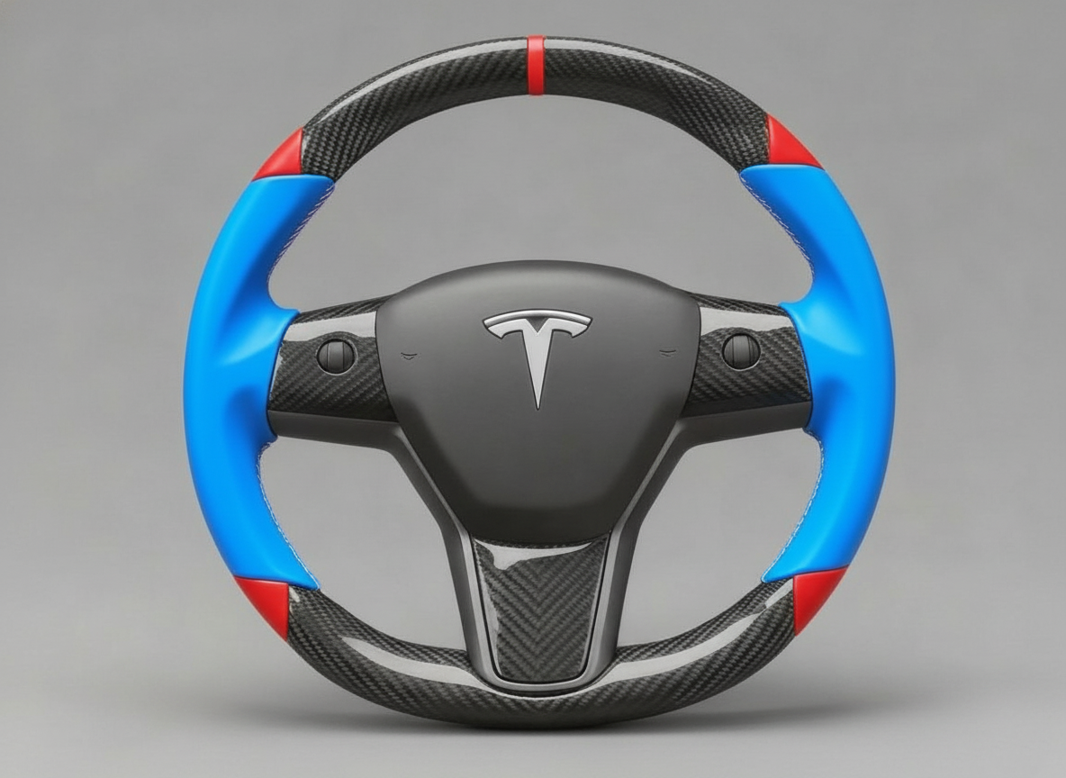
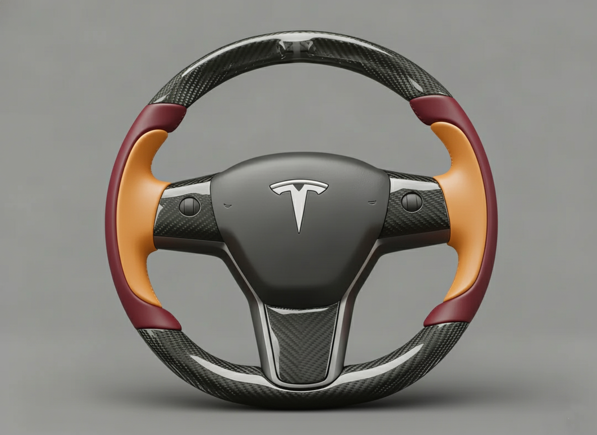
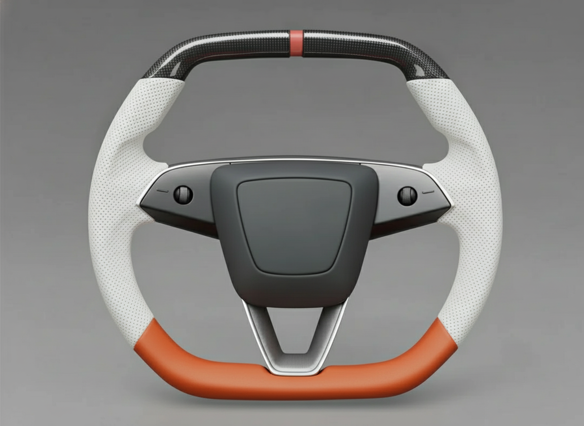
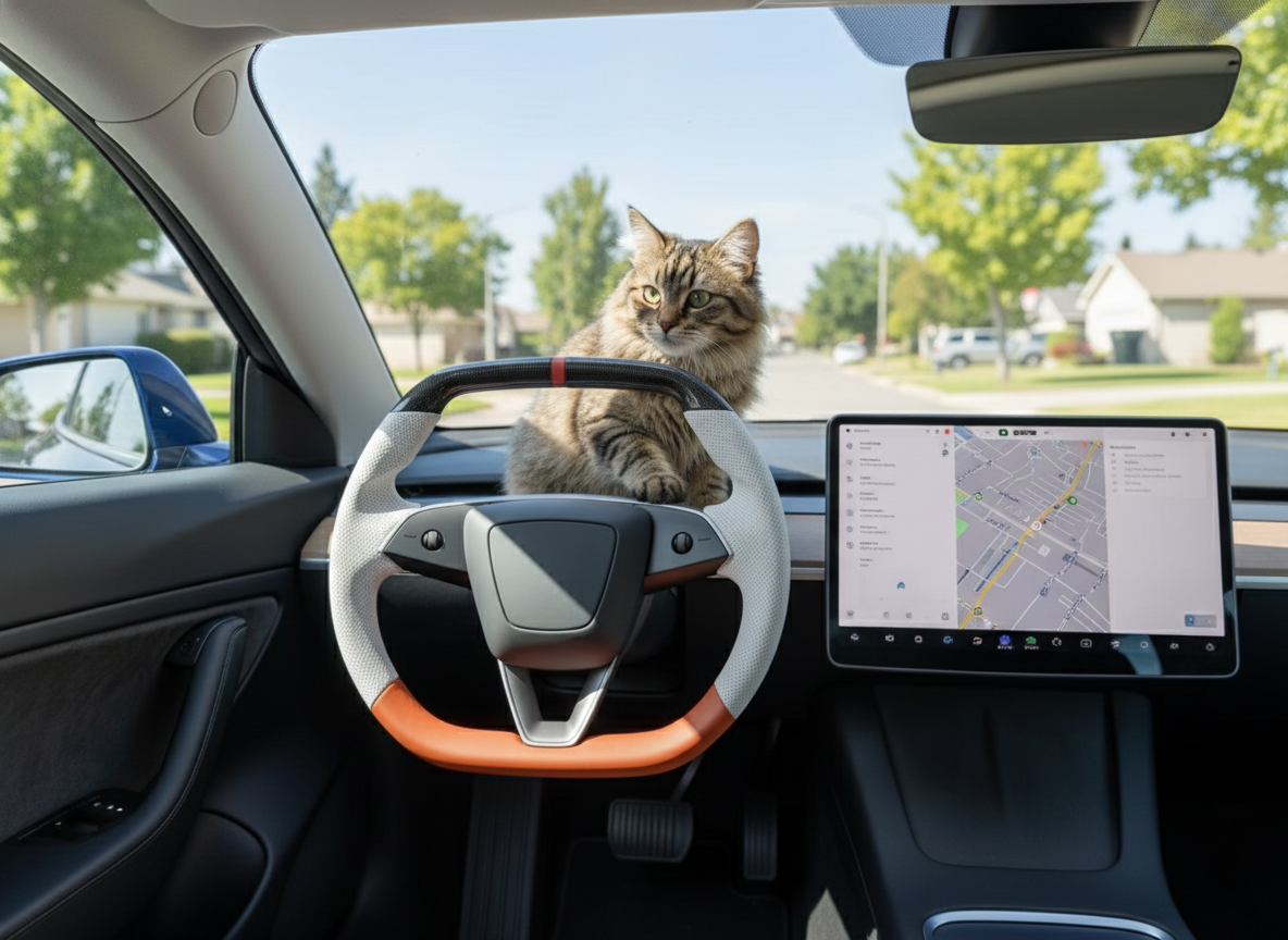
The failure of the Tesla Model 3 steering wheel heating is mostly due to firmware lag or abnormal electronic fuses.
Operationally, please first press and hold the dual scroll wheels on the steering wheel for 10 seconds to reboot the vehicle's infotainment system.
Starting from the 2021 model year, this vehicle uses electronic fuses. If the surface does not reach the 35-degree constant temperature standard within 3 minutes after turning on the heating in the screen's climate interface, it is usually hardware damage to the internal resistance wire or the front control module.
Fuses
The steering wheel heating circuit of the Tesla Model 3 does not contain a physical fuse that can be manually replaced by the user.
This power supply is managed by MOSFET solid-state electronic fuses (E-Fuse) on the VCFRONT or VCLEFT body controller motherboard.
When the system reads, at a millisecond frequency, that the current of the heating coil exceeds the normal range of 6A-10A, or the loop resistance is close to 0Ω, the power supply will be forcibly cut off within 10 milliseconds.
Restoring the power supply to this system does not require buying new parts, but requires clearing the internal error codes of the controller through a specific software reboot or vehicle deep sleep operation.
Cannot Find the Fuse
North American car owners are accustomed to looking for blown metal wires in the black plastic box in the driver's side footwell or the frunk. Fuel vehicles rely on physical circuits breaking to prevent wiring harness fires. The low-voltage electrical architecture of the Model 3 completely abandons the independent cabin fuse box.
Abandoning the independent cabin fuse box has drastically reduced the number of physical fuses in the whole vehicle from 40 to 60 in traditional models to less than 5. The remaining few are sealed above the high-voltage battery pack or within safety modules, dedicated to providing physical redundancy for airbag deployment and Pyrotechnic disconnects. Comfort electronics are no longer allocated independent physical power lines. The power supply for steering wheel heating has been integrated into Zonal Controllers.
Zonal controllers mainly refer to the VCFRONT (front body controller) installed in the front compartment and the VCLEFT (left body controller) under the A-pillar. The controller motherboards are covered with high-density semiconductor patch components. Traditional manually plugged components have been replaced by MOSFETs (Metal-Oxide-Semiconductor Field-Effect Transistors) soldered using Surface-Mount Technology (SMT). MOSFETs form the physical foundation of solid-state electronic fuses (E-Fuse).
The solid-state electronic fuse is responsible for connecting the 12V or 15.5V (for lithium battery models) power supply of the steering wheel heating loop, and performing continuous low-level data collection. When the heating pad inside the leather cover is turned on, the system reads the amperage in the loop at a millisecond frequency. The rated power consumption of a normally functioning Model 3 steering wheel heating element is typically between 40 watts and 60 watts.
With a power consumption of 40 watts to 60 watts at a voltage of 12V to 15.5V, the system will read a continuous operating current of 2.5A to 5.0A. Strict overcurrent protection thresholds are preset in the VCLEFT controller. Once the read value exceeds 10A and lasts for more than 10 milliseconds, the MOSFET will flip its state to forcefully cut off the power supply. The forceful cutoff is to protect the extremely thin internal 22 AWG gauge power supply wiring harness.
Protecting the extremely thin internal power supply wiring harness is absolutely necessary because the steering wheel needs to continuously rotate during use, causing mechanical wear. The hub connecting the fixed end of the steering column and the rotating steering wheel is the Clock Spring. Multiple Flat Flexible Cables (FFC) are wound inside, responsible for transmitting heating power and scroll wheel data. After the flexible cables undergo tens of thousands of frictions, the insulation layer can become damaged.
Damage to the insulation layer allows the exposed copper wires carrying positive voltage to touch the metal aluminum steering column base behind them. The moment of touch creates a Short to Ground, causing the loop resistance to drop to nearly 0.1Ω. At this time, the instantaneous current will surge to over 30A or even 50A. In older fuel cars, severe instantaneous current would blow a 50-cent plastic fuse.
Blowing a plastic fuse produces a burnt smell and visible broken wires, but in the architecture of the Model 3, everything happens silently. The MOSFET of the VCLEFT controller closes within a few microseconds, blocking the short-circuit current and preventing the clock spring ribbon cable from catching fire. Subsequently, the computer will write a non-permanent fault code regarding "Steering Wheel Heater Overcurrent" into the system background log.
Writing a non-permanent fault code will force the heating function to remain in the "off" state until the system determines the danger is resolved. Technicians at North American Tesla Service Centers plug a dedicated ethernet cable into the Fakra connector on the driver's side. Through the Toolbox 3.0 diagnostic software, the technician can read the exact timestamp when the specific resistance deviation and current anomaly occurred.
The exact timestamp, accurate to the millisecond, helps technicians recreate the rotation angle and stress situation of the steering wheel when the fault occurred. Besides reading log files, the original intention of the engineering team in designing a fuseless system was to adapt to a highly integrated manufacturing process. On the assembly line at the Fremont factory in California, eliminating hundreds of connectors can shorten the Takt Time of each car by about 45 seconds.
Shortening the Takt Time by about 45 seconds can save enormous manufacturing costs on an assembly line producing 500,000 vehicles annually. In order to completely discard the fuse boxes of the old era, Tesla engineers recalibrated the entire low-level power supply and protection parameters:
-
Older heating harnesses were mostly 18 AWG, while the Model 3 uses 22 AWG copper wires to reduce the overall vehicle harness weight by about 1.5kg.
-
Thermal fuses require heat accumulation for 100-500 milliseconds to completely break, while MOSFET solid-state cutoff takes only an extremely short 0.01 milliseconds.
-
The old solution required going to an auto parts store to buy a $0.5-$2 USD part for manual replacement, whereas the new solution is automatically reset by the in-car MCU sending a command to the gateway.
-
The old solution only had two absolute states: on and off, while the new solution can record current changes at the 0.1A level and generate visual charts in the diagnostic software.
When an owner complains that the steering wheel fails to heat up on a -10 degrees Celsius morning, maintenance personnel do not need to blindly dismantle the airbag. The diagnostic chart will show that within the first 3 seconds of being powered on, the resistance abnormally drifted from the normal 2.8Ω to over 15Ω. The abnormally elevated resistance triggered the Open Circuit protection logic of the electronic fuse.
The Open Circuit protection logic cuts off the power, preventing localized arcing and high temperatures at the loose connection. After seeing the 15Ω data, the technician can order a new clock spring assembly through the parts system, usually with the part number 1097662-00-G. The repair process skips the inefficient step of testing fuses one by one as in traditional cars, compressing the Flat Rate for a single repair from 1.5 hours down to 0.4 hours.
How the Computer Controls Power
When the driver taps the steering wheel heating icon on the 15-inch center touchscreen, the system does not engage any mechanical relays. The screen assembly sends a digital signal via the vehicle's Local Interconnect Network (LIN bus) at a baud rate of 19.2 kbps. The digital signal containing the turn-on command travels along the copper twisted pair inside the dashboard, reaching the left body controller (VCLEFT) in less than 5 milliseconds.
The left body controller (VCLEFT) is installed behind the plastic trim panel on the left side of the driver's side footwell. Its printed circuit board (PCB) integrates multiple Smart High-Side Switches manufactured by semiconductor companies like Infineon. A silicon-based MOSFET, measuring only 5mm x 5mm, replaces the bulky 15A mechanical relays found in traditional cars, governing the output of 15.5V low-voltage direct current.
Governing the output of 15.5V low-voltage direct current is not just a simple power-on action. The MOSFET chip integrates a Current Sense Pin, which can sample the actual load at the output terminal at a frequency of 1000 times per second. Such current data is converted into an analog voltage signal in real-time and fed into the 32-bit microprocessor on the controller motherboard, through which the microprocessor continuously monitors the health status of the heating circuit.
The microprocessor uses this to continuously monitor the health status of the heating circuit to prevent abnormalities in the clock spring or heating pad. A normal heating coil consists of special alloy wires sewn under a polyurethane foam layer, with a designed standard resistance between 2.5Ω and 3.5Ω. Under a supply voltage of 15.5V, according to Ohm's law, the normal operating current read by the controller will stabilize in the range of 4.4A to 6.2A.
Stabilizing within the 4.4A to 6.2A range indicates that the steering wheel is in a safe heating process. The vehicle requires frequent turning of the steering wheel while driving. After undergoing over 50,000 physical twists, the insulation layer of the internal Clock Spring ribbon cable may become damaged. Once the damaged exposed copper wire touches the grounded aluminum alloy steering column base behind it, the physical resistance of the circuit will instantly drop to nearly 0.05Ω.
The physical resistance of the circuit instantly dropping to nearly 0.05Ω will cause a short circuit and generate an extremely high instantaneous current. According to calculations, a Short to Ground will instantly produce a theoretical current exceeding 300A, enough to burn the wiring harness and cause a fire within 0.5 seconds. When the smart MOSFET hardware protection circuit within the VCLEFT detects that the current exceeds the absolute threshold of 15A, it will forcefully disconnect the internal transistor within 10 microseconds.
Forcefully disconnecting the internal transistor within 10 microseconds ensures that the temperature of the 20 AWG physical wiring harness does not exceed the insulation melting point of 105 degrees Celsius. After the power is cut off, the microprocessor will write a 16-hex fault code, such as a013_heaterOvercurrent, into the controller's Non-Volatile Memory (NVM). The code is permanently locked, and the system will prevent the MOSFET from closing again until an external diagnostic device intervenes.
Until the external diagnostic device intervenes, the vehicle will remain in a safe power-off state. The Tesla service technician connects a laptop to the Fakra ethernet port under the center console and opens the Toolbox 3.0 diagnostic software. The software interface reads real-time telemetry data from the VCLEFT. The screen displays a target current of 0.0A, and the electronic fuse status is marked as "Tripped," saving the time of using a multimeter to measure physical pins.
Saving the time of using a multimeter to measure physical pins, the technician can clearly compare the current fault through the data matrix in the software. The diagnostic system relies on preset current and resistance parameter models to distinguish different hardware failure modes. The table below details how the VCLEFT controller executes precise computer logic judgment and power-off protection for various states of the steering wheel heating circuit based on specific electrical measurement values.
| Circuit Operating State | Measured Resistance Range | Expected Current Reading (15.5V) | MOSFET Action Logic | Fault Code Trigger Condition |
|---|---|---|---|---|
| Normal Heating | 2.5Ω - 3.5Ω | 4.4A - 6.2A | Remains Closed | None |
| Clock Spring Broken (Open Circuit) | > 1000Ω | 0.0A - 0.1A | Maintains power but logs anomaly | No load detected for 3 consecutive seconds |
| Partial Short (Overcurrent) | 1.0Ω - 2.0Ω | 7.7A - 15.5A | Soft Trip (Software cutoff) | Current exceeds 10A for 50 milliseconds |
| Short to Ground (Extreme) | < 0.1Ω | > 30.0A (Instantaneous) | Hard Trip (Hardware instant cutoff) | Hardware low-level sensing, cut off within 10 microseconds |
Executing precise computer logic judgment and power-off protection for various states of the steering wheel heating circuit based on specific electrical measurement values transforms traditional physical maintenance into data analysis. If the diagnostic software shows a continuous current draw of 0.0A, the system determines it as an Open Circuit state. Based on this data, the technician can confirm that the heating coil or clock spring has completely broken internally, judging physical hardware damage without disassembling the steering wheel.
Able to judge hardware physical damage without disassembling the steering wheel, the technician can requisition a brand new steering wheel assembly or clock spring component with part number 1097662-00-G from the warehouse. After replacing the new hardware worth $650, the controller's solid-state fuse remains intact and soldered to the motherboard. The technician simply needs to click "Clear Faults" in the Toolbox 3.0 software, sending an 8-byte reset command over the local area network to the VCLEFT.
By sending an 8-byte reset command over the local area network to the VCLEFT, the controller's microprocessor will erase the overcurrent history in the memory. After the system is reset, the MOSFET is allowed to conduct again, entering the monitoring cycle again at a frequency of 1000 times per second. The steering wheel temperature sensor (NTC thermistor) will then feed back real-time data to the computer, rising from 10 degrees Celsius to 35 degrees Celsius, declaring the repair complete.
How to Restore Power
Upon discovering there is no physical 10A fuse to replace, the only way to restore the 15.5V steering wheel heating power supply is to interact with the vehicle's low-level software. When the left body controller (VCLEFT) detects a current exceeding 10A, it will write an exception code into its Non-Volatile Random-Access Memory (NVRAM). The written exception code will remain active in the background, preventing the controller from outputting voltage. The most basic action to lift the protection lockout is to initiate a reset using the steering wheel scroll wheels. Initiating a reset using the steering wheel scroll wheels takes very little time, requiring only that the driver execute a simple two-button long-press command while parked.
Simultaneously press and hold the left and right scroll wheels on the steering wheel for about 10 to 15 seconds until the 15-inch center touchscreen turns completely black.
Until the 15-inch center touchscreen turns completely black, the Media Control Unit (MCU) equipped with an AMD Ryzen processor cuts off the video output and begins rebooting the Linux operating system. During the system reboot cycle lasting up to 45 seconds, the MCU will send status reset commands to all zonal controllers across the vehicle via the CAN bus at a baud rate of 500 kbps. Upon receiving the reset signal, the zonal controllers throughout the vehicle will briefly suspend their current logic cycles and attempt to retest the disconnected heating loop with a micro-current of 50mA.
Retesting the disconnected heating loop with a 50mA micro-current can determine whether the steering wheel resistance has returned to the normal 2.5Ω to 3.5Ω range. If the temporary resistance drift disappears, the electronic fuse's MOSFET switch will re-close, and the steering wheel will once again draw a normal operating current of 4.4A to 6.2A. The steering wheel drawing normal operating current again signifies a successful soft reboot, but if a solidified fault exists on the physical level, a deeper vehicle sleep and power-off operation must be executed.
The vehicle sleep and power-off operation will force the high-voltage contactors to open, completely severing the physical connection between the 400V traction battery pack and the DC-to-DC converter (DC-DC). Severing the physical connection is to stop the 15.5V lithium-ion low-voltage battery from supplying power to the secondary modules in the car, prompting the capacitors on the VCLEFT motherboard to fully discharge to 0V.
On the screen, tap Controls, Safety, Power Off in sequence, and remain absolutely still in the driver's seat waiting for 3 to 5 minutes.
Remaining absolutely still in the driver's seat waiting for 3 to 5 minutes ensures that the vehicle's low-voltage network is completely powered off, thereby erasing volatile memory fault codes like a013_heaterOvercurrent. After erasing the volatile memory fault codes, the driver pressing the brake pedal can wake the vehicle, and the controller will execute a fresh Power-On Self-Test (POST) the moment power is applied. The POST will be accompanied by the "click" sound of the high-voltage contactors closing, and the DC-DC converter will resume outputting up to 2500W of power to the low-voltage network.
After resuming the output of up to 2500W of power to the low-voltage network, the microprocessor again sends a test pulse to the heating element; if the measured resistance is higher than 1.0Ω, heating permission will be issued. Heating permission will be issued to the MOSFET gate, and the steering wheel surface temperature will climb to 35 degrees Celsius over the next 3 minutes relying on a 60W output power. Climbing to 35 degrees Celsius indicates that the deep power cycle cleared the logic suspension; if the temperature remains at room temperature after 3 minutes of waiting, system low-level telemetry data must be read using a diagnostic tool.
Reading system low-level telemetry data via diagnostic tools requires the owner to bypass the conventional user interface to acquire real-time parameters from 3 CAN buses and 2 LIN buses. Acquiring real-time parameters requires activating a special page reserved for technicians inside the car, thereby viewing the real-time amperage of the electronic fuse.
Enter the software menu, press and hold the vehicle model text for 3 seconds then release, and type "service" into the pop-up password box to enter Service Mode.
After entering Service Mode, the screen border turns red and displays the internal node topology of the Model 3; navigating to the Chassis menu allows viewing the target and actual current of the steering wheel heating. If the target and actual current show a target of 5.0A while the actual output remains at 0.0A, and carries a "Trip" label, it indicates both manual reset procedures have failed. The failure of both manual reset procedures indicates that the fault has shifted from the software level to physical hardware, and a technician from a Tesla Service Center must take over the vehicle to perform a factory-level reset.
A factory-level reset relies on the technician plugging a laptop into the Fakra ethernet port under the center console and establishing a 100 Mbps local area network connection in the Toolbox 3.0 diagnostic software. After establishing the 100 Mbps LAN connection, the technician clicks the "Clear Faults" button, and an 8-byte hexadecimal reset command is pushed to the body controller.
The reset command pushed to the body controller forces an overwrite of the protection flag in the non-volatile memory. If the current still reads 0.0A after the test, the technician will place an order to procure the clock spring with part number 1097662-00-G, which retails for approximately $110 in North America. The replacement job for the ~$110 clock spring typically consumes 0.4 standard labor hours in the official work order system.
After consuming 0.4 standard labor hours to complete the physical ribbon cable replacement, the act of disconnecting the 22 AWG power harness will once again trigger an Open Circuit fault code with infinite resistance. Triggering the Open Circuit fault code with infinite resistance requires the technician, after resetting the airbag, to send the 8-byte command one last time to erase the alarm, allowing the system to restart closed-loop monitoring at a 1000 Hz frequency. After restarting closed-loop monitoring, the 15.5V power will flow smoothly through the new clock spring ribbon cable, and the cabin heating function is declared completely restored.
Firmware
The Model 3's steering wheel heating power is allocated by the Front Body Control Module (VCFRONT) via software.
When the vehicle receives OTA updates, the firmware handshake protocol of the internal modules sometimes times out.
This manifests on the screen as the heating icon being at level 3 (red), but the Steering Column Control Module (SCCM) is not outputting the 50W heating power.
Troubleshooting software issues takes very little time and does not require dismantling physical parts. The point of failure can be determined by operating the UI panel, the Tesla App, or reading Service Mode codes.
Testing the Heating Function
The Model 3 steering wheel heating grid has a rated power of 50W, controlled by the VCFRONT module via the CAN bus. The initial step to test the heating function is to observe the HVAC panel at the bottom of the 15-inch center screen. Tap the steering wheel icon; under normal conditions, the icon will turn red and display visual cues of level 1, 2, or 3 wavy lines.
After the icon turns red, the system allocates 12V power to output approximately 4.1A of direct current. If the icon on the screen automatically reverts to gray within 2 to 3 seconds after turning red, it indicates that the wake-up signal sent from VCFRONT to the Steering Column Control Module (SCCM) experienced a timeout. Signal timeouts typically occur within 48 hours after the vehicle has just completed a major OTA firmware upgrade.
A way to bypass screen UI communication faults is to use the Tesla App to issue an independent command. The app version needs to be v4.20 or above. Keep the vehicle in Park (P), and enter the Climate panel within the app. Tap the steering wheel heating button in the upper right corner, and observe the feedback animation on the app interface.
The app command is dispatched via the LTE network, bypassing the MCU (Media Control Unit), straight to the vehicle's chassis modules. After the command is dispatched, place your hands on the 3 o'clock and 9 o'clock grip areas of the steering wheel and wait. Under standard working conditions, the temperature of the leather surface will climb from ambient temperature to a range of about 32°C to 35°C within 3 minutes.
The prerequisite for reaching 35°C is that the vehicle's high-voltage battery SOC (State of Charge) is above 20%. When the battery level is below 20%, the energy management system will forcibly cut off the power requests for the PTC heater and the steering wheel heating grid. The screen UI interface might still display a red heating icon, but the actual output power is restricted to 0W by the firmware.
Aside from battery level restrictions, voice activation can also test the firmware's instruction parsing pathway. Press the right scroll wheel on the steering wheel and say, "Turn on steering wheel heater". Observe the voice recognition waveform appearing at the top of the screen, followed by the execution status prompt box returned by the low-level modules.
After the prompt box confirms execution, the existing ambient temperature in the cabin needs to be read. The Model 3's heating logic has a built-in Thermal Protection Threshold. When the cabin temperature sensor reading exceeds 28°C, the steering wheel heating power is automatically derated to below 15W.
After derating to 15W, it is difficult for human skin to perceive a significant temperature rise. To rule out somatic misjudgments caused by ambient temperature, one needs to read the low-level data from the vehicle's engineering interface. Long-press the "Model 3" model text on the screen for 5 seconds to enter the hidden Service Mode interface.
The Climate sub-menu in Service Mode provides real-time impedance and power flow information. Click on the Steering sub-interface below this level and look for the "SteerWheelHeater Duty Cycle" data stream. This data reflects the Pulse Width Modulation (PWM) duty cycle reading allocated by the firmware to the heating grid.
When the heating command is normally executed, the PWM duty cycle parameter will jump between 80% and 100%. If the system is in the heating command ON state, but the PWM duty cycle consistently shows 0%, accompanied by a red exclamation mark warning nearby, it indicates that the firmware has completely locked out the hardware power supply end.
The scenario of a locked-out power supply end can be re-tested and verified through third-party API ports.
-
Call the official Tesla Fleet API interface and send a POST request `api/1/vehicles/{id}/command/set_steering_wheel_heater`.
-
Set the `on` parameter in the request code to `true` and observe the JSON formatted report returned by the terminal.
-
The report will contain code text such as `result: true` or `reason: "timeout"`.
If the HTTP status code returns 200 but the heating still fails, it proves that the TCP connection pathway between the cloud and the vehicle is normal. The fault point is narrowed down to the short 60-centimeter LIN bus data stream between the VCFRONT and the SCCM inside the car. After confirming the data stream anomaly, an underlying reboot/clear command must be executed.
Before executing the low-level command, turn off Sentry Mode and all preset temperature hold functions. Remove all items occupying seats in the car and close the doors properly. Tap the Power Off button in the Safety menu on the screen. Sit in the driver's seat remaining absolutely still to ensure the weight sensor does not trigger the wake-up mechanism.
Wait for a full 5 minutes until the ambient sounds inside the car (like the hum of the coolant pump) completely disappear. After 5 minutes, press the brake pedal deeply. The 12V low-voltage system will reload the low-level firmware registry. Turn on the heating function again for a loop test. At this time, use an infrared thermometer pointed at the 12 o'clock position on the top of the steering wheel to precisely record data.
The emissivity of the infrared thermometer should be set to 0.95 to match the surface material properties of polyurethane or synthetic leather. Record the surface temperature every 30 seconds. A normal heating curve should present a linear trajectory of rising 3°C to 5°C per minute.
If the temperature curve is a horizontal straight line with no fluctuation at all, combined with the previously captured data showing a 0% PWM duty cycle, it can be concluded that the existing firmware package has suffered irreversible file corruption. Open the Tesla App and submit a service ticket with the timestamped API timeout record and photos of the infrared thermometer readings.
Reboot & Power Off
The Model 3's center screen is driven by an MCU module based on the AMD Ryzen or Intel Atom architecture, responsible for rendering the steering wheel heating UI. By shifting into Park and simultaneously pressing the scroll wheels on both sides of the steering wheel (which have 2N damping) for 10 seconds, the system cuts off the 12V power supply pins to the MCU. Once the power is cut, the 15-inch LCD screen will instantly go black, indicating that the Linux kernel-based underlying operating system has begun executing process-kill codes.
The process-kill procedure of the Linux kernel-based operating system takes about 45 seconds, after which the system will reload the GUI interface and display the silver Tesla logo on the screen. Within 20 seconds after the logo appears, the MCU sends Ping command packets via the ethernet cable to the vehicle's gateway module at a rate of 1 per second. The successful return of the Ping packets confirms the re-establishment of the handshake between the UI and the underlying hardware control local area network communication.
After the communication handshake of the underlying hardware control local area network is completed, tapping the heating icon on the screen will cause the MCU to send a power request frame to the CAN node at address `0x318`. If the steering wheel surface temperature does not rise to the set 32°C threshold within 3 minutes, it indicates that the dual scroll wheel reboot only cleared the VRAM cache. The Front Body Control Module (VCFRONT) responsible for the physical power supply, which is outside the VRAM cache, may still be locked in a fail-safe state.
The VCFRONT module in the fail-safe state requires a deep power-off procedure executed via the screen to force the discharge of residual charges in its internal capacitors. Sit in the driver's seat, close all four doors, and tap Controls, Safety, Power Off sequentially on the screen. The high-voltage contactors will emit a metallic disconnect sound of about 65 decibels. The metallic disconnect sound represents that the physical connection between the 400V high-voltage battery pack and the DC-DC converter is severed, and the 12V low-voltage system enters an independent discharge cycle.
| Operation Command Name | Target Reset Module | Time Required to Execute | Triggered Voltage Change |
|---|---|---|---|
| Soft Reboot | MCU Media Control Unit | 65 Seconds | 12V drops to 0V instantly then recovers |
| Power Off | VCFRONT / SCCM | 300 Seconds | Internal SRAM drops below 0.5V |
| Hard Reset | Whole Vehicle 12V/16V Bus | 600 Seconds | Float voltage drops from 13.5V to 0V |
The 12V low-voltage system entering an independent discharge cycle requires the occupant to remain absolutely still in the seat for up to 5 minutes to avoid triggering the recognition threshold of the weight sensor. Once the weight sensor detects a pressure change exceeding 15 pounds, it will wake up the dormant gateway module and reconnect the relays of up to 300A. A 5-minute rest period is sufficient for the SRAM voltage in the VCFRONT module to drop below 0.5V, clearing all temporary heating disable flags.
After clearing all temporary heating disable flags, pressing the brake pedal deeply for about 3 centimeters of travel will prompt the pressure sensor to generate a 2.5V analog signal to wake up the whole vehicle system. The moment the system wakes up, the VCFRONT performs a 150-millisecond impedance probe on the Steering Column Control Module (SCCM) to detect the 2.8-ohm heating grid inside the steering wheel. If the impedance probe passes, the SCCM will allow a maximum of 4.1A of direct current to enter the steering wheel through the flexible printed circuit cable.
If there are micron-level physical cracks in the flexible printed circuit cable entering the steering wheel, the transient surge current upon repowering will trigger secondary protection at the firmware level. The secondary protection will instantly limit the heating power output from the normal 50W to 0.5W, causing the steering wheel surface temperature to remain at an ambient temperature of 22°C. To completely eliminate the low-level electrical state lockout, the frunk must be opened to execute a physical level 12V or 16V low-voltage battery disconnect procedure.
Executing the physical level 12V or 16V low-voltage battery disconnect procedure requires removing the plastic air intake cover panel near the windshield, which has 7 clips. Use a 10mm socket wrench to turn counterclockwise 3 times to loosen the fastening nut on the negative terminal of the lead-acid or lithium battery. After removing the negative terminal, wrap the metal connector with insulating tape to prevent it from springing back and touching the 12.6V battery post.
After preventing it from springing back and touching the 12.6V battery post, the low-voltage network will still be maintained by the high-voltage battery pack through the DC-DC converter with a float voltage of about 13.5V. Go to the underside of the right rear seat and pull out the First Responder Loop plug with the orange tag. After pulling out the plug with the orange tag, all electronic modules in the car will lose low-voltage power, and multimeter readings at all fuse terminals will return completely to zero.
The state where multimeter readings at all fuse terminals return completely to zero needs to be maintained for at least 10 minutes to ensure the solid-state capacitors on the motherboard are fully discharged. After 10 minutes, first plug back the orange high-voltage disconnect plug with 2 waterproof sealing rings under the rear seat. Return to the frunk, put the negative metal terminal back onto the battery post, and tighten it using a torque wrench set to 6 Newton-meters.
The moment it is tightened to 6 Newton-meters, the siren at the front of the vehicle will emit a short 120-decibel chirp, marking that the anti-theft module is back online. The center screen in the cabin takes about 3 minutes to reload the 3.5GB firmware system image file. By sending the `heater_on` command through version v4.20 of the Tesla App, an infrared thermal imager should be able to observe a 35°C high-temperature zone appearing at the 3 o'clock and 9 o'clock positions of the steering wheel.
Finding Error Codes
After the center screen undergoes a complete cold boot of the 12V low-voltage system, the UI interface will load the current branch firmware with version number 2023.44.30.8. After the firmware is loaded, tap the car icon in the bottom left corner of the 15-inch screen to enter the Controls menu, then scroll to the Software tab at the bottom. The right side of the tab will show the vehicle's VIN and processor type; press and hold the gray "Model 3" lettering on the screen with your index finger for 5 seconds.
Release your finger after 5 seconds, and a pop-up window with a blinking cursor for password input will appear in the center of the screen. Type the lowercase word "service" on the pop-up QWERTY virtual keyboard and click the blue confirm button; the system's low-level diagnostic gateway will be activated. Once the diagnostic gateway is activated, a red border will appear around the screen, indicating that the vehicle has officially entered the privileged Service Mode.
The main interface of Service Mode is divided into multiple subsystem grids; the left navigation bar lists 14 different domain controllers from the high-voltage battery pack to the body controllers. Scroll down the left list, find the Climate panel with a snowflake and fan icon, and click to enter. After entering the Climate panel, the topology map on the right will display real-time readings from the 6 temperature sensors inside the car and the operating power of the PTC heater.
Below the operating power is a secondary collapsible menu named Steering. Expanding this menu allows you to view the communication status of the Steering Column Control Module (SCCM). This menu contains a data stream node named SteerWheelHeater; when normally powered on, this node will display an impedance of 2.8 ohms and a current of 4.1 amps. If a yellow warning triangle appears next to the data stream node, it indicates that the Controller Area Network (CAN) bus has captured abnormal voltage fluctuations.
Abnormal voltage fluctuations are generated by the system into specific Diagnostic Trouble Codes (DTC) stored in the flash memory of the Front Body Control Module (VCFRONT). Click the Active Alerts icon in the upper right corner of the screen, and the drop-down menu will list all error logs triggered by the vehicle in the past 14 days. The error logs are sorted in reverse chronological order by timestamp, and the format includes the specific year, month, day, hour, minute, second, and occurrence time accurate to the millisecond.
The occurrence time accurate to the millisecond is followed closely by a string of alphanumeric DTC codes. A steering wheel heating failure usually corresponds to `VCFRONT_a192_steerWheelHeater`. The `VCFRONT_a192` code indicates that the body controller sent 12V power to the steering wheel but did not receive the expected closed-loop current within the 150-millisecond detection cycle. The lack of the expected closed-loop current will trigger another underlying supplementary code, shown in the log as `SCCM_a045_heaterCircuitOpen`.
The code `SCCM_a045_heaterCircuitOpen` indicates that the Steering Column Control Module has detected a physical disconnection in the wiring.
The judgment threshold for a disconnected line is set as the loop impedance exceeding 100 ohms continuously for 3 seconds, at which point the system will automatically cut off the 50W output power to prevent localized overheating and fires.
After cutting off the 50W output power, the error status text recorded in the log will change from Active to Latched, requiring manual intervention.
The manual intervention steps require the user to record the highlighted red code with the timestamp, using a smartphone camera in landscape mode to take a picture of the entire screen containing the VIN. The resolution of the photo must be clear enough to distinguish hexadecimal auxiliary codes like `UI_a014_hvacPanel` or those involving LIN bus communication timeouts. The combination of hexadecimal auxiliary codes can help backend engineers at the Tesla Fremont factory construct a complete system-level failure model.
The system-level failure model distinguishes whether it is packet loss from firmware during an OTA update, or a mechanical break in the flexible ribbon cable after 10,000 twists. At the bottom of the Service Mode interface, click the Clear Alerts button to try to clear the temporary fault codes stored in SRAM. After the temporary fault codes are cleared, while in Park (P), press the brake pedal again for about 3 centimeters of travel to initiate a new steering wheel heating request test.
The new steering wheel heating request test will force the VCFRONT to send a wake-up frame again via the CAN node at address 0x318. If the exact same red `VCFRONT_a192` warning pops up again on the screen within 2.5 seconds after the system sends the wake-up frame... The reappearance of the exact same `VCFRONT_a192` red warning confirms permanent hardware damage to the NTC thermistor or the heating grid inside the steering wheel.
Once permanent hardware damage is verified by the low-level logs, exiting Service Mode requires pressing and holding the red exit icon in the upper right corner of the screen for 3 seconds. The exit operation will restore the vehicle's ethernet gateway to the standard user mode and generate a diagnostic package file sized at approximately 2.5MB. The diagnostic package file will be stored in a hidden partition of the vehicle's built-in 64GB eMMC storage chip, waiting for the cloud network to fetch it.
The cloud network fetch process is triggered by the Service module in the Tesla App; the user inputs the previously photographed `SCCM_a045` code into the description box of the service ticket. The App packages the user's input data and uploads it via the LTE network to the North American headquarters' servers, generating a digitized repair work order that includes the vehicle's current mileage (e.g., 32,000 miles). After the digitized repair work order is generated, the system will automatically match the user with the nearest after-sales service center and generate an order list for a new steering wheel replacement assembly with the part number 1456822-00-A.
Fixes
Fixing the Model 3 steering wheel temperature loss requires troubleshooting in the order of the MCU (Media Control Unit), SCCM (Steering Column Control Module), and physical wiring harnesses.
80% of software blockages can be resolved by triggering a VCFRONT electronic reset, either by long-pressing the dual scroll wheels for 10 seconds or letting the car sit powered off for 2 minutes.
If it falls on the hardware level, it is mostly seen as pin oxidation on the Clock Spring or an open circuit in the internal 35W heating wire.
Outside the warranty period, the total material and labor cost to replace the assembly at a Tesla Service Center ranges from $500 to $650.
Triggering Electronic Reset
The Model 3 uses a low-voltage power architecture; the 2021 and earlier models are equipped with a 12V lead-acid battery, while the 2022 versions with the AMD Ryzen chip were upgraded to a 16V lithium-ion battery. The steering wheel heating is uniformly scheduled for power by the Front Body Controller (VCFRONT). When the heating icon on the center screen is tapped and the physical surface temperature still does not rise while the ambient environment is 68°F (20°C), a lag has occurred in the communication between the Controller Area Network (CAN bus) and the Steering Column Control Module (SCCM). Clearing the communication fault requires executing specific software and hardware reset procedures.
Executing the initial reset procedure requires operations targeting the Media Control Unit (MCU). Shift the vehicle into Park (P), press down on the metal scroll wheels on the left and right sides of the steering wheel simultaneously with both hands, and maintain the pressure. The pressing time must be strictly maintained between 10 and 15 seconds. The 15-inch center display will experience a brief freeze, then the backlight voltage will drop, and the screen will turn completely black.
After the screen turns black, release the scroll wheels, and the system bottom layer begins to reload the Linux-based operating system. Wait for about 30 to 45 seconds; the silver Tesla "T" logo will light up in the center of the screen, showing that the Bootloader is guiding the startup. During the 45-second boot time window, the vehicle's turn signals, audio system, and HVAC blower will temporarily cease to operate.
Wait for the LTE or WiFi cellular network icon in the upper right corner of the screen to show a full signal before engaging in UI interface interactions. Open the bottom climate menu and tap the steering wheel heating icon to the highest level. Over the next 60 seconds, hold the 10 o'clock and 2 o'clock positions of the steering wheel with your hands; a properly working 35W heating wire will cause the surface leather temperature to rise by about 10°F (5.5°C) within one minute.
If no temperature rise is detected after the MCU soft reboot, the problem points to an unresponsive internal state within the VCFRONT or SCCM. The scroll wheel reboot only cycled the power to the infotainment system's processor, while the vehicle's low-voltage subsystem hardware remains powered on. Cutting off the power circuit to peripheral controllers requires forcing a deep power-off sequence.
Sit in the driver's seat and ensure that all four doors, as well as the frunk and trunk latches, are completely closed. Tap the car icon in the bottom left corner of the screen to enter Settings, find the "Safety" menu, and scroll to the very bottom of the page. Tap the red Power Off button; the screen will instantly turn off, and the overhead reading lights and footwell lighting will be powered off synchronously.
Stay in the seat and keep your body absolutely still. The Occupant Classification Sensor (OCS) inside the seat cushion is in real-time monitoring mode; shifting your center of gravity or pulling the door open will trigger the high-voltage contactor to close, and the 400V battery pack will send power to the DC-DC converter, interrupting the sleep process. Turn off the screen of the smartphone containing the Tesla App, or temporarily disable the Bluetooth function to prevent the phone's Bluetooth Low Energy (BLE) signal from waking the vehicle.
Strictly adhere to a 2 to 5 minute rest and wait time. Approaching the 2-minute mark, a dull mechanical "click" sound will emanate from beneath the rear chassis of the vehicle. The high-voltage battery contactor physically disconnects, and the 16V low-voltage battery loses its continuous source of replenishment. The electronic fuse (e-fuse) network inside the VCFRONT completely discharges its electrical charge at this moment, achieving a power-off on the physical level.
Step firmly on the brake pedal to end the power-off sleep cycle. The screen backlight wakes up, and the system takes about 10 seconds to restore touch responsiveness to the user interface. The VCFRONT performs a cold boot self-test, polls all connected modules via the CAN bus, and sends commands to the SCCM. The system reads the real-time resistance value of the internal heating loop of the steering wheel and checks if this value is within the standard range of 2.0 to 4.0 ohms.
If the read resistance value meets the 2.0 to 4.0 ohms specification, the electronic fuse will reset its previous tripped anti-blowout state and reopen the 12V/16V current path flowing to the steering wheel. To verify whether the reset is successful, one must follow a checklist containing specific test data:
-
Use a smartphone (iOS or Android) connected to a 4G/5G cellular network or WiFi to open the Tesla App and send a heating command remotely.
-
Observe the cabin interior temperature sensor reading displayed on the App interface to confirm the ambient temperature baseline remains below 70°F (21°C).
-
Aim a digital infrared thermometer vertically at the synthetic leather surface at the top of the steering wheel, maintaining a distance within 2 inches (5 cm).
-
Record the initial Fahrenheit reading before starting, keep the heating function running at full load for 3 minutes, and then take a second measurement.
-
If the hardware reset is successful, the surface temperature data from the second measurement will infinitely approach the 95°F (35°C) hardware protection upper limit written into the system.
Reinstalling Firmware
Heating commands issued via screen UI interaction are transmitted over the CAN bus at a baud rate of 500 kbps. When sector corruption occurs in the binary file of the underlying firmware, the command packets received by the Steering Column Control Module (SCCM) will experience packet loss.
Performing an overwrite installation requires bypassing the conventional user interface to enter Tesla's engineering-level Service Mode. Shift into Park (P) and tap the "Software" menu item on the 15-inch screen. Locate the vehicle name "Model 3" text, press and hold that area with your finger for 2 to 3 seconds, and then release.
After releasing your finger, a prompt window with a text input box will pop up in the center of the screen. Type the English word "service" on the full keyboard interface and click confirm. After system verification passes, a red border with a wrench icon will appear around the edges of the screen.
The UI with a red border signifies that the vehicle has switched to the background diagnostic environment. Click the "Software" tab on the left menu bar, then click the "Software Reinstall" button. The system will send a data request to Tesla's AWS servers located in Austin, Texas.
The sent request contains the vehicle's unique 17-digit VIN and the currently running system version number (e.g., 2023.44.30.8). After verifying the VIN, the server begins to dispatch a complete installation compressed package ranging in size between 1.5GB and 2.8GB.
The download process relies on the vehicle's built-in LTE communication module or a connected 2.4GHz/5GHz WiFi network. In a home WiFi environment reaching 50 Mbps, the entire download phase takes about 10 to 15 minutes. Once the download progress bar hits 100%, the background decompression program starts.
The background decompression program extracts the encrypted .tgz file into the 64GB eMMC or NVMe storage chip inside the MCU. After extraction is complete, the screen will pop up a 2-minute countdown installation confirmation window.
In the 1st minute after the installation sequence starts, the vehicle will actively disconnect the contactors of the 400V high-voltage battery pack. Two crisp metallic disconnect sounds will be heard in the cabin, and all non-essential high-voltage power-consuming equipment will stop running. The 16V lithium-ion low-voltage battery begins to take over the basic power supply for the entire vehicle's controllers.
Relying on the low-voltage power supply, the system begins flashing low-level codes to dozens of independent controllers across the vehicle one by one. The old cache data of the Front Body Controller (VCFRONT) and SCCM are cleared during this phase. The firmware rewrite process usually lasts 30 to 45 minutes, during which the center screen will restart multiple times and light up to a black screen.
While the screen is in a black or refreshing state, the electronic buttons on the doors (E-latch) and the window lift motors become unresponsive. The in-car HVAC system shuts down, and the vents stop blowing warm air above 68°F (20°C). A driver remaining in the car must pull the mechanical door handle at the front end of the door panel to open the door.
Pulling the mechanical door handle or stepping on the brake pedal will send a wake-up signal to the gateway, interrupting the ongoing system flashing. An interrupted flash will cause the motherboard to rollback to the previous backup version, resulting in a failed reinstallation. Remain seated and absolutely still until the screen displays the green text "Update Complete".
Seeing the green prompt text means the system has loaded the bug-free new control code into the SCCM's motherboard flash memory. Click the "Exit" button in the upper right corner to exit Service Mode and return to the everyday main interface. Lightly touch the steering wheel heating icon on the climate panel, and the motherboard will generate an unobstructed control command.
The control command is delivered to the micro-relay beneath the steering column via the CAN bus with an extremely low latency of 10 milliseconds. The relay closes and allows a constant voltage of 12V to 16V to flow to the 35W polyimide heating pad on the outer ring of the steering wheel. Open the Tesla App installed on an iOS device to observe the status; the red wavy lines on the heating icon will remain constantly lit.
After the icon remains constantly lit for 3 minutes, use a Bluetooth-connected diagnostic tool or an infrared thermometer to read surface data. The temperature of the leather grip areas at 3 o'clock and 9 o'clock on the steering wheel should stabilize around the 90°F (32°C) range. A reading meeting the standard proves that the software code error causing the heating freeze has been thoroughly cleared.
Clearing software errors cannot fix a broken Clock Spring ribbon cable caused by physical external pulling forces.
A physically broken ribbon cable will return an infinite (∞) measured resistance value signal to the VCFRONT. An infinite resistance value will be judged by the system's low-level code as a hardware short-circuit risk. Even after completing the reinstallation and overwrite of all system files, the motherboard will still refuse to allocate any power to the steering wheel's heating module.
Hardware Troubleshooting
The infinite (∞) measured resistance value signal will force the system to turn off output, and the focus of troubleshooting must shift from the code layer to the physical structure. The physical structure inside the steering column consists of the Front Body Controller (VCFRONT), Steering Column Control Module (SCCM), and the 35W polyimide heating wire on the steering wheel skeleton. Using a T25 Torx screwdriver to remove the two fixing screws at the bottom of the steering column allows the removal of the plastic trim panel wrapping this set of hardware.
After removing the plastic trim panel, the SCCM module and its internal Clock Spring ribbon cable box will be exposed. The clock spring is a flat, flexible ribbon cable wound inside a plastic shell, responsible for maintaining electrical connection while the steering wheel rotates 2.0 turns to the left and right. Prolonged and high-frequency physical friction can cause this ribbon cable, which is only 0.15mm thick, to experience metal fatigue or even breakage.
A broken ribbon cable will completely cut off the path for 12V or 16V direct current to reach the heating pad above. Switch a digital multimeter to the ohms (Ω) setting, and unplug the white 4-pin harness connector linking the steering wheel above the SCCM. Insert the red and black test probes into pins 1 and 2 of the connector respectively; under normal conditions, the multimeter screen should display a resistance reading of 2.0 to 4.0 ohms.
If the reading deviates from the normal range of 2.0 to 4.0 ohms and shows less than 1.0 ohm, it indicates a physical short circuit has occurred in the internal heating wire. If the reading displays "OL" (Over Load) or infinity, it confirms an open circuit in the heating loop. Facing a short or open circuit, Tesla Service Centers do not offer repair items for individually sewing heating wires; technicians will order a brand new steering wheel assembly (e.g., part number 1490214-00-B) for an entire replacement.
Entirely replacing the steering wheel assembly requires first removing the central SRS airbag module. Insert a flat-headed hex wrench with a 5mm diameter into the blind holes at the bottom left and right sides of the steering wheel. Push inward against the internal metal spring latches to release the airbag, and then use a 10mm socket wrench to unplug the yellow high-voltage connector on the back of the airbag.
After unplugging the yellow high-voltage connector, place the airbag module on an insulating rubber mat away from static electricity. Fixing the center of the steering wheel skeleton onto the steering column splines is a 16mm hex flange bolt. Using a torque wrench with an extension bar, unscrew this bolt counterclockwise. Grasp the steering wheel at the 3 o'clock and 9 o'clock positions with both hands, and pull it backward parallelly to remove the old steering wheel from the steering shaft.
After removing the old steering wheel, align the brand new heated steering wheel assembly with the spline slots on the steering shaft and push it in. Replace it with a brand new 16mm central fixing bolt containing blue thread-locking adhesive. Use a torque wrench to tighten this central bolt clockwise, and the force must strictly adhere to the 50 Nm (Newton-meters) torque standard specified in the Tesla repair manual.
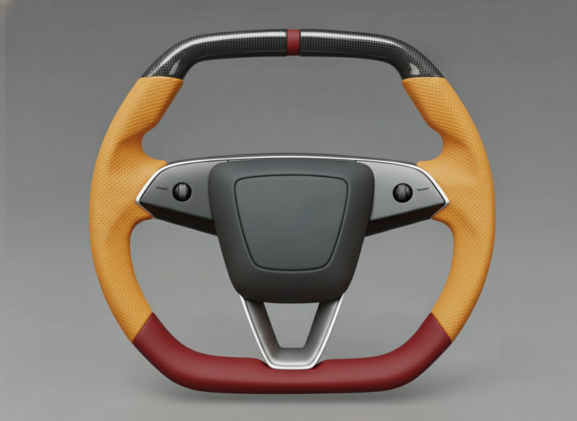
Once the torque standard is met, press the black 2-pin connector responsible for controlling the multi-function scroll wheels and heating module inside into the corresponding slot. If a third-party aftermarket half-Yoke steering wheel was modified, the terminal pins of this 2-pin connector are very prone to coming loose during the stripping and re-crimping process. Check the terminals for any pin push-out phenomenon to ensure the metal tabs are completely locked into the barbs of the plastic housing.
After confirming the pins inside the plastic housing are securely locked, re-install the airbag following the original steps and snap the plastic steering column trim panel back tightly. For a Model 3 that is outside the 4-year or 50,000-mile (80,000 km) Basic Vehicle Limited Warranty period, hardware troubleshooting and replacement will incur materials and Labor costs borne by the car owner. When generating the repair bill, the Service Center will list the various charge details according to the specific damaged components.
| Hardware Fault Component | Quantitative Characteristic of Fault Phenomenon | Replacement Part Number Example | Estimated Out-of-Warranty Cost (USD) |
|---|---|---|---|
| Steering Wheel Assembly | Multimeter reads connector resistance > 10 ohms or OL | 1490214-00-B / 1490214-00-C | $500 - $650 |
| Steering Column Control Module (SCCM) | Heating disconnects when wheel turns > 90 degrees | 1097662-00-G | $300 - $400 |
| Internal Harness Pin Push-out | 2-pin connector terminal falls out under 5N pull force | Re-crimp or replace local harness | $80 - $150 (Labor fee) |
After the charge details are listed and the bill is paid by the car owner, the technician will use the internal diagnostic software Tesla Toolbox 3 to configure the newly assembled hardware. The software writes the new serial number into the SCCM and clears the heating wire short or open circuit fault codes stored in the gateway. Driving the vehicle out of the Service Center workshop under an outdoor ambient temperature of 40°F (4°C), the new hardware can output a constant 35W power within 2 minutes, and the leather surface temperature will climb steadily to 95°F (35°C).